News

TÜV SÜD National Engineering Laboratory launches real-time subsea meter calibration tool

TÜV SÜD National Engineering Laboratory (NEL) today launches NEL-SURE, a real-time software tool for the verification of subsea multiphase flow meters (MPFM), that will help operators to optimise reservoir management and revenues.

As the oil & gas industry exploits deeper fields, routine calibration is unviable due to the excessive cost of removing subsea MPFMs for laboratory-based validation. While MPFMs are calibrated before installation, laboratory-based flow regimes differ greatly to actual subsea conditions. Consequently, over time significant measurement errors result in fiscal loss, for both operators and taxation authorities. 

NEL-SURE provides in-situ, continuous calibration of MPFMs and uses a traffic light system to alert operators to a meter’s health. The software can also accommodate a virtual meter to provide a secondary measurement for verification of the MPFM’s output. This will help to improve process and control decision making, increase productivity and safety, and reduce environmental impacts through the early identification of potential system failures.

Marc Laing, Head of Software & Modelling at TÜV SÜD National Engineering Laboratory, said: “While industry relies on MPFMs as inaccessible reservoirs are exploited, the lack of validation possibilities has impacted the accurate allocation and taxation of hydrocarbon assets. The challenge is to take the calibration process from the laboratory and move it to the ‘in situ’ location. This will ensure that flow meter verification accounts for the different effects of pressure, temperature and fluids at each individual well, allowing operators to have ongoing confidence in the measurements.

“NEL-SURE meets this challenge by reducing financial exposure and delivering operators increased confidence in the deployment and use of MPFMs. These intelligent meter health checks will save industry millions of pounds per year from unnecessary calibrations, maintenance and shutdowns,” concluded Laing.

NEL-SURE was developed at NEL’s Advanced Multiphase Facility, which has a test range (operating pressures, temperatures, flowrates and metrology) beyond the capability of any other laboratory in the world. As the UK’s National Measurement Institute for flow and density measurement, NEL has captured flow meter data over the last 30 years which has been used to develop NEL-SURE to be a completely impartial MPFM validation solution that is agnostic of any meter manufacturer.

Tips for choosing a 3D vision system

With four times as many as colour receptors as humans, the Mantis shrimp has the most impressive eyes in nature.  Manufacturers have long relied on human vision for complex picking and assembly processes, but 3D vision systems are beginning to replicate the capability of human vision in robotics. Here, Nigel Smith, managing director of Shibaura Machine, formerly Toshiba Machine, partner, TM Robotics, gives three rules to live by when choosing a 3D vision system for manufacturing.

Rule one: Abandon CAD

Advanced 3D vision systems are a stark contrast to the vision software of manufacturing’s past. Many existing systems still require professional CAD programming to ensure the robot can recognise shapes. However, even after programming, this software can have difficulties recognising multiple items at once.

A common application for vision systems is removing and sorting items from a bin. While CAD-based systems can identify items in a bin, the challenge is recognising the position of each item when presented in a random order — let alone determining the best method for the robot pick them in.

Advanced vision systems eliminate this problem by using passive imaging to enable the robot to automatically identify items, regardless of their shape or order.

Shibaura Machine’s vision system, TSVision3D, for example, uses two high-speed cameras to continuously capture 3D images. Using intelligent software, the system can process these images and identify the exact position of an item. This determines the most logical order to pick them up and does so with sub millimetre accuracy, with the same ease as a human worker.

Rule two: Mimic human perception

Deploying a robot for bin-picking isn’t advantageous if the robot cannot identify the edges of the bin. Considering the speed and strength of most 6-axis robots, hitting the box sides could easily halt production or damage the product.

Some manufacturers believe that motion stereo systems can effectively imitate a human’s perception of an item. Motion stereo systems use one camera, usually mounted on a robotic arm, to enable the system to move and take two or more photographs of an object. However, these systems require absolute precision as even the slightest movement can cause disparities in data and skew the measurement.

For manufacturers hoping to automate their box-picking processes, they should identify whether the system has a collision avoidance function. Advanced systems, including TSVision3D, enable the system to be programmed according to the size of the bin, ensuring the robot can dive into the box without a hitch.

Rule three: Simplify installation  

Automation for jobs like bin-picking are designed to free manual operators from repetitive and menial tasks and speed up operations. However, some traditional vision systems involved multiple hurdles to implement, including longwinded installation methods and high levels of technical know-how.

Using 3D vision systems for bin-picking, cycle times can be as fast as 0.7 seconds. But, these productivity gains are useless if implementation of the software has high costs for time and staff resources.

When choosing a system, manufacturers must strike a balance between potential productivity gains and the resources required for installation. Today, manufacturers should opt for software that anyone, even with minimal training, can understand.

Eyes are a testament to evolution’s creativity. While they all have the same basic duty, the more advanced the vision system, the more information it can acquire. When choosing a vision system for manufacturing applications, manufacturers should consider how the system will improve their process, how it will manage complex requirements and how easy it is to understand and implement it.

TE Connectivity encourages diversity in tech with $3.5M African Heritage Scholarship Program

In an effort to further diversify its workforce and bring new opportunities in the technology industry to top-performing minority students, TE Connectivity, a world leader in connectivity and sensors, has committed $3.5 million toward a new scholarship and internship program for students who identify as Black or African-American.

TE Connectivity has committed $3.5 million to help promote diversity in STEM.

Rising sophomores are eligible to apply for the program, which would begin with a paid internship the summer after their sophomore year at one of several TE sites throughout the United States. Students who successfully complete the internship would receive a scholarship of up to $22,500, based on need and educational costs, and be invited back for a second internship the following summer. The scholarship would then be eligible for renewal for their senior year. TE expects a new cohort of students will join the African Heritage Scholarship Program each year for the next five years.

“We are excited to invest in the TE Connectivity African Heritage Scholarship to help attract diverse talent to our company’s pipeline of potential future employees and the STEM industry as a whole,” said CEO Terrence Curtin. “We believe that a more inclusive and diverse workforce fosters innovation and I look forward to the new ideas this group of interns will bring to TE for years to come.”

For the first summer of the program in 2022, internships are available in engineering, product management, supply chain, operations and sales at TE sites in six different states. TE’s internship program is designed to fill the company’s leadership development programs and early career roles. In addition to real world job experience with a global impact, TE’s interns experience a wide range of professional development workshops covering financial literacy, corporate communications and personal branding. Other programming includes global networking events, community involvement opportunities and executive exposure.

Students entering their sophomore year in the 2021-2022 academic year may learn more about the TE Connectivity African Heritage Scholarship at te.com/scholarships.

Case Study: iSMART Research Group and Woollam IR-Vase II

Quantum Design UK and Ireland (QDUKI), in collaboration with the Medical Technologies Innovation Facility (MTIF) and Nottingham Trent University are proud to present this case study from the iSMART (innovation in Surfaces, Materials and Related Technologies) research group, led by Dr. Nikolaos Kalfagiannis and co-workers from Université de Poitiers, Sheffield Hallam University and the University of Nottingham.

The iSMART group have focused their research around the optical and electronic properties of materials and thin films for nano-photonic and electronic applications, specifically metal-oxides. QDUKI supplied the J A Woollam Infrared Variable Angle Spectroscopic Ellipsometer (IR VASE-II) capable of providing the optical constants of materials in the extended spectral range from 1.6 – 40 microns. Indeed, QDUKI and MTIF have entered into a partnership to provide access to potential users to view, and measure trial samples on, the J. A. Woollam IR VASE II Spectroscopic Ellipsometer on an ad hoc contract basis.

Case Study

In the iSMART (innovation in Surfaces, MAterials and Related Technologies) research group (embedded within the Medical Technologies Innovation Facility – MTIF, based in Nottingham, UK) we focus our research interest around the optical and electronic properties of materials and thin films for nano-photonic and electronic applications. One such example of a family of materials related to both applications, mentioned above, are the metal-oxides. Metal oxides have emerged as promising material candidates in various electronic and optoelectronic applications offering unique advantages such as high mobility, wide bandgap (transparent in the visible range), and the ability to be controllably doped. Importantly, in iSMART we have developed routes to different scalable deposition techniques for such materials (from wet chemistry methods to vacuum deposition techniques).

The J A Woollam Infrared Variable Angle Spectroscopic Ellipsometer Mark II at MTIF

Spectroscopic ellipsometry (SE) is a highly sophisticated and non-destructive metrology tool for determining the optical constants of materials. iSMART is equipped with a J. A. Woollam Infrared Variable Angle Spectroscopic Ellipsometer (IR VASE II), capable of providing the optical constants of materials in the extended spectral range from 1.6 – 40 microns.

Only two ellipsometers of this type currently exist in the whole of the UK, with one such system being located at MTIF which is available for contract development work and academic partnership for all UK industry and any Research institutes. The IR VASE II was supplied by Quantum Design UK and Ireland Ltd. who are the official representatives of J. A. Woollam inc. Quantum Design UK and Ireland Ltd. and MTIF have entered into a partnership to provide access to potential users to view, and measure trial samples on, the J. A. Woollam IR VASE II Spectroscopic Ellipsometer on an ad hoc contract basis.

High Vacuum Deposition Chamber in MTIF

Our partnership with The University of Nottingham (contact person: Dr. Christopher Mellor) allows for this spectral range to be extended further, using a J.A. Woollam M-2000DI spectroscopic ellipsometer, to include the near infrared, visible and ultraviolet wavelengths (1.69 – 0.193 microns). This combined capability, offers one of the widest spectral ranges available world-wide (0.19 – 40 microns). By extracting the exact optical constants, we also enable the determination of material properties such as charge transport (mobility, doping concentration, resistivity), lattice vibration (phonon absorption) and band structure (via interband transitions and band gaps).

These fundamental properties of semiconducting materials are key parameters for opto-electronic applications. In a recent work, Dr. Nikolaos Kalfagiannis and co-workers from Université de Poitiers, Sheffield Hallam University and The University of Nottingham, employ SE in the extended spectral range (0.2 – 40 microns) and develop the methodology for the accurate determination of the free carrier transport properties of transparent conductive oxides and discriminate between the different scattering mechanisms(grain boundary scattering, inter-grain scattering and ionised impurity scattering) in an effort to clarify the conduction mechanisms of such materials and define their range of application.

As part of the partnership, QDUKI and MTIF are co-hosting a Spectroscopic Ellipsometry Workshop in September, where Dr. Kalfagiannis will give several talks. This free of charge workshop is aimed at both experienced ellipsometry users as well as people new to ellipsometry.

Are you seeking to better understand the optical and electronic properties of materials or thin films for nanophotonic or electronic applications? Find out more

Titan bridges troubled waters for flow meter installation

Titan Enterprises have released video tutorials illustrating correct wiring of their pulse precision flow measurement devices to support customers with the installation of flow meters into their applications.

Within the flow metering industry, wiring a flow meter is often second nature to experienced engineers and may seem intuitive for established customers. However, Titan’s flow meters are used throughout a wide variety of industries, processes and applications. New customers unfamiliar with our flow metering solutions, may find themselves in turbulent water if the meters are wired incorrectly during the installation process.

The majority of Titan’s flow meters use transistors which can be damaged through simple wiring mistakes, resulting in a defunct meter before the customer has even started! By providing customers with clear visual methods of how to install a flow meter and correct wiring to the power source, we are aiming to save customers time and money in what are essentially preventable errors.

“Although all Titan flow measurement devices are supported with written data and instruction sheets, through our ISO 9001 examination of returns and call logs, we have found that a large percentage of flow meter installation issues result from mis-wiring.” states Jeremy Thorne, Production Manager with Titan Enterprises.

Research shows that a large proportion of people consult a video when learning something new. Neil Hannay, Senior R&D Engineer at Titan Enterprises, commented: “For customers who are new to our flow meters, visual demonstrations for wiring the flow measurement devices will help to reduce simple errors that cost customers time and money.”

“YouTube is a very accessible platform and is a great delivery method for Titan flow meter instructional videos. As we don’t carry out on-site flow meter installations ourselves, providing visual tutorials are a useful way to illustrate correct wiring methods which we anticipate will reduce the number of unnecessary returns and rebuilds.”

Video tutorials currently available on the Titan website (www.flowmeters.co.uk) include wiring requirements for:

  • Titan’s beverage flow meter.
  • Turbine flow meters within Titan’s 800 series, 900 series and FT2 flow transducers.
  • Titan’s OG2 oval gear flow meter.

We will be expanding Titan’s flow metering instruction videos to include our full range of flow meter devices to help customers get the best out of their meters and to ensure that the meters are performing to their most efficient levels within customer applications.

For further information on flow measurement devices to suit specific applications, please contact Titan Enterprises on +44 (0)1935 812790 or sales@flowmeters.co.uk. For Titan’s video tutorials, visit our website’s Customer Resources at www.flowmeters.co.uk/flow-meter-installation-tutorials/


AVT Reliability partnership with Teledyne FLIR will enhance thermal imaging offer

AVT Reliability has announced a partnership with world-leading thermal imaging camera manufacturer Teledyne FLIR.

The partnership with the Oregon, USA, headquartered company, will enable AVT Reliability to offer industrial clients state-of-the-art cameras and software for the condition monitoring of assets, further enhancing its UK and Ireland thermal imaging offer.

Lee McFarlane, Group Technical Director at AVT Reliability, which is part of the AES Engineering Reliability Group, said: “The quality of a thermal imaging camera is crucial to the safe collection of detailed and accurate data to inform a proactive maintenance plan.

“Teledyne FLIR is world-renowned for the innovation of its design and the quality of its thermal imaging equipment, which we have utilised for decades in our service business.

“It was a natural fit for both parties that AVT Reliability UK and Ireland become a channel partner in the condition monitoring sector. We’re confident that their range of advanced products will bring enormous benefits to our clients across the UK and Ireland.”

Handheld thermal imaging cameras can be used as part of a condition based maintenance programme on electrical, static and rotating equipment.

Lee McFarlane added: “The range of cameras available is extensive, depending on their application and budget. Additionally, AVT Reliability’s certified consultants can offer practical and technical guidance to clients, to ensure they apply the technology for optimum benefit.”

Contrinex’s Smart Sensors keep shafts turning with low-cost bearing condition monitoring

Contrinex Smart Sensors, available from PLUS Automation, offer a low-cost single sensor solution for condition-based monitoring of critical rotating machinery. They are able to monitor multiple parameters in real-time, including unexpected levels of vibration, increased bearing temperature or irregular radial deflections of a shaft. These highly versatile sensors provide a flexible, cost-effective solution that maximises data availability without adding complexity to the system.

Customer application

Engineers constantly seek solutions to minimise machine downtime without risking costly or perhaps dangerous breakdowns. It is a dilemma faced by engineers and designers worldwide, especially in sectors like heavy industry, mining, marine engineering, oil and gas, green energy and rail operations where rotating machinery is common-place and the machinery is often remotely located or inaccessible.

Bearing failure is a significant risk in equipment with rotating elements and it is generally sign-posted in its early stages by increased levels of vibration and a rise in bearing temperature.

Typically, this risk is managed by frequent inspection and maintenance of bearings, but condition-based monitoring (CBM) has become the preferred approach for cost-effective maintenance operations. CBM uses sensor technology to extract real-time data from machinery, developing a performance profile that identifies potential failures before they bring operations to a ‘grinding halt’.

Designers have to balance the desire to collect as much data as possible, on vibration, deflection, temperature and operating hours, which might all help predict an imminent breakdown, while keeping cost and complexity to a minimum.

Specifying multiple sensors meets the data-collection needs, but is a costly approach, often requiring significant compromise in mechanical design.

Customer solution

Contrinex Multi-Mode Smart Sensors fulfil the application’s requirements without compromise, using their multi-function technology. A single Smart Sensor can monitor multiple parameters including deflection, vibration, temperature, linear position, angular displacement and cycle count. Each of these measurements may be reported as process data or event data, while cumulative operating parameters are recorded in the sensor’s on-board storage.

The user-defined operating modes enable a single sensor to provide a range of functions. On the rotating machinery, it is mounted in either a bearing housing or adjacent to a shaft, to monitor for unexpected levels of vibration, increased bearing temperature or irregular radial deflections of the shaft. The sensor’s IO-Link functionality provides plug-and-play replacement of damaged sensors, without any loss of functionality and without any need for configuration.

image006.jpg

Dual-channel operation is another valuable feature of the Smart Sensor range. Should a critical event occur, the sensor delivers a high-speed notification directly to the control system, bypassing the IO-Link communications channel and initiating a shut-down sequence immediately. This avoids further, costly damage and minimizes subsequent process downtime.

Smart Sensors are exceptionally reliable, making them ideal for installation in remote locations where day-to-day access can be impossible. In wind turbines, rail cars, drag-lines, marine powerplants, paper mills, drilling platforms, construction equipment, heavy-duty pumps and a host of similar installations, these highly versatile sensors tick all the boxes.

Contrinex inductive Smart Sensors are designed with the needs of OEMs and System Integrators in mind to provide an unobtrusive fit-and-forget solution. For flexible, cost-effective CBM solutions that maximize data availability without adding complexity, Contrinex Multi-Mode Smart Sensors deliver complete peace of mind

The sensor’s high corrosion resistance has contributed to excellent reliability providing the customer with a cost-effective solution for a simple, fit-and-forget system.

The ABC of Milling

Milling, drilling, thread tapping – there are very few switchgear manufacturers who love metalworking. Fortunately, there is a solution! Automated machining centres such as the Perforex MT can help as Mark Guest, Product Manager for Power Distribution Systems at Rittal, explains.

The following three tips show how it can be used to its full advantage.

The task of machining enclosures, housings and mounting plates takes switchgear manufacturers a lot of time if they have to carry out the work by hand. It can easily add up to four hours or more – reading through plans, marking out holes, tapping threads, deburring cut-outs and then cleaning the machined parts. In a small company that doesn’t have a dedicated metalworking department, electricians and switchgear engineers end up doing the work, which takes up valuable time that they lose when it comes to building and wiring the switchgear.

The Perforex MT has an automatic tool changer and tool magazine that can hold up to 21 tools. It takes care of all work in a single pass, without operators having to intervene and can machine all materials generally used in switchgear, such as steel, stainless steel, aluminium, copper and plastic. Enclosures made of stainless steel can be machined better and more efficiently on the Perforex LC.

75 PER CENT FASTER

State-of-the-art milling machines can cut machining time by up to 75 per cent. The savings are even more impressive when it comes to laser machining systems, which cut the processing time for steel enclosures by up to 85 per cent. When working with the Perforex MT, there are a few tips that can help companies achieve these savings:

Clamping on the Perforex MT:

With the right accessories, panels can be clamped in place so as to reduce vibrations and bulging.  The end result is that tools last longer.

TIP 1: CLAMP COMPONENTS TO MINIMISE VIBRATION

Clamping has a major influence on the service life of milling tools. Wear occurs at the point at which the cutting edge of a milling tool comes into contact with the material it is machining. The more defined this contact point is, the more efficiently material can be removed and the less wear there is on the tool. The experts at Rittal Automation Systems recommend ensuring that components are securely clamped in place, which reduces relative movement between the milling tool and the component.

  • Use as many clamping elements as possible, such as manual clamps and pneumatic clamping elements.
  • Line clamping elements with cushioning to prevent bulging in the components.
  • Brace the component at close intervals using spacer bolts or, better still, brush strips. This ensures the cutting edge can work more effectively.
  • Use a clamping frame when working on small enclosures. This enables you to machine several boxes at the same time.
  • These measures help to reduce the movement of the components and extend the service life of tools.

TIP 2: ADJUST FEED FLEXIBLY

How can you extend the service life of milling tools? In general, the faster the feed speed, the shorter the service life, and the lower the feed speed, the longer the service life.  Feed should therefore be adjusted to requirements.  Tools should also be properly cooled and cooling lubrication systems regularly checked, because the strength of machining tools declines as temperatures rise.

Shortly before a milling tool breaks, the metal will melt, usually at a localised point – the cutting edge disappears and the tool breaks against the cut edge of the component.  Speed and feed should also be coordinated.  The machine manufacturer will provide initial guide values, but it is a good idea to document feed and speed values during operation and optimise them for your own product mix.

 TIP 3: SELECT THE RIGHT TOOLS 

Besides feed, speed and cooling, the milling tool itself also determines its own useful life to a large extent. For instance, the more cutting edges a milling tool has, the more edges engage during one revolution, the more material is removed in one revolution and the less stress is placed on each cutting edge. This extends the service life of the milling tool. By contrast, higher feed speeds lead to more tool change intervals. If higher speeds are necessary or longer tool change intervals are required, carbide milling tools with four edges can be used. However, not all carbide milling tools can cope with the vibrations on the components. This is another area where users should follow the recommendations of specialists from Rittal Automation Systems, who have the right product for every application scenario.

Vision Engineering achieves ISO 13485:2016

Vision Engineering, a 63 year old British leading designer and manufacturer of high-quality visual measurement and inspection technologies, has attained ISO 13485:2016 and EN ISO 13485:2016 accreditation from the British Standards Institution (BSI) and is now a BSI accredited contract manufacturer of mechanical, electronic, electrical, and optical medical assemblies and components.

International Recognition

The ISO 13485:2016 standard is an internationally recognised standard of quality and safety for the medical device industry and provides stringent guidelines for medical device manufacture. The certification process recognises that Vision Engineering meets all the requirements to manufacture medical devices and components and builds on the ISO9001:2015 quality systems already in place at Vision Engineering.

Modern Manufacturing Facilities

Vision Engineering’s full service modern manufacturing facility includes design, machine shops, paint shop, clean room and assembly. It is replicated in the USA, with a wholly owned full service manufacturing facility in Connecticut.

In addition to its manufacturing services capability, Vision Engineering supplies non-contact and contact optical and digital microscopy and measuring systems to a wide range of global manufacturers, including medical device, aerospace, automotive, defence and their multi-tier supply chains.

Mark Curtis, Managing Director, Vision Engineering comments: “We are delighted to be awarded the ISO standard ISO 13485:2016 for our manufacturing facility. This ISO standards confirmation is a key statement of our ability to address the requirements of our manufacturing customers across the world and provide certainty of the quality of mechanical, electronic, electrical, and optical medical assemblies and components.

“It will help enormously in our worldwide business with medical device companies and also with Vision Engineering’s Manufacturing Services business line for wider sub contract manufacturing opportunities.”

New Pressure Scanner launches with World First Features

A new digital pressure scanner launched by US manufacturer, Scanivalve Corporation, is set to delight engineers with a number of staggering new features.

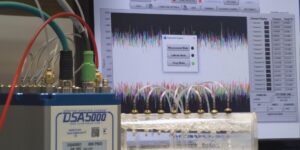
After two years in development, Scanivalve’s talented engineers have broken new ground with the DSA5000 as it delivers a number of world firsts.

Uniquely, the DSA5000 utilises an individual 24-bit A/D converter and RTD for each sensor allowing fully and truly synchronous data collection. Data can be delivered at rates of up to 5,000Hz per channel in a wide of engineering units.

Through revolutionary ‘ring-architecture’ capability, multiple DSA5000s can be connected together through miniature Ethernet connectors. This delivers the industry’s only integrated, multi-drop architecture, industrial network configuration for pressure scanning instrumentation. This creates an isolated, mini-network where the “master” unit serves as a single point of communications for all scanners in the mini-network. Scanners are automatically identified, easily configured, and accurately synchronized. Data from all scanners are merged together to provide a single output data file with pressure and temperature values from all of the connected Scanivalve 5000 series scanners.

Whilst smart, fast and highly accurate, the DSA5000 is designed withstand extreme environments too. Its IP67 rated aluminium case is rugged but lightweight, with an option to install a self-controlled internal heater which allows operation in ambient temperatures down to -50°C. The DSA5000 can also be fitted with an optional shock-mount kit, which has been tested to MIL-STG 810G Cat. 24, 514.6.

Operating a wide range of pressure ranges from 4”H2O (0.18psi) to 1,000psi (at launch) in several pneumatic configurations means a DSA5000 can be configured for low pressure aerodynamic tests, high pressure compressor tests, and everything in-between.

Paul Crowhurst, Managing Director at Evolution Measurement said, “This is a truly exciting product. Never before have we seen this level of capability in a pressure instrument. This is going to revolutionise aerodynamic development as our world embarks on more advanced airframe and gas turbine engine development.”

For more details on the DSA5000, full details are available at www.evolutionmeasurement.com or call +44 (0)1264 316470.