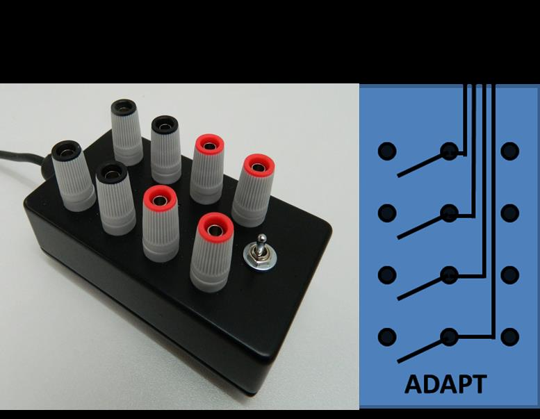
 The ADAPT is a novel way many top end calibration laboratories are connecting sensors and sources to measuring equipment such as platinum resistance thermometers (PRTs) to a temperature indicator and performing simulations.
Use 1: The ADAPT can be used as a break-out box to connect 1 or 2 resistance thermometers to a single channel of a temperature indicator or a logger. Ideal for connecting various types of inputs to instruments that use connectors such as those made by Lemo which are fitted to the Isotech MilliK, see Figure 1.
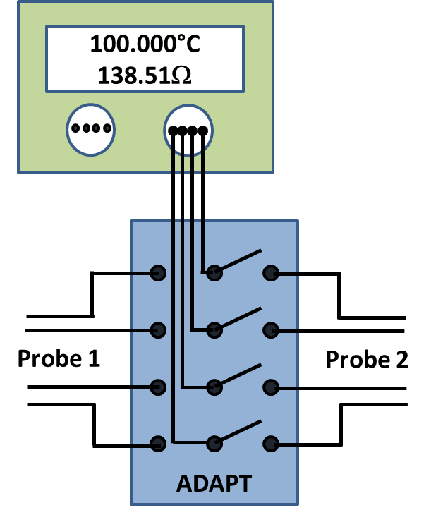
Figure 1: Connecting 1 or 2 PRTs to a channel of an Isotech MilliK.
Use 2: As Use 1 above but connecting resistors into a meter.

Figure 2: Connecting a standard resistor to a digital multimeter and using the other terminals shorted to zero the meter.
Use 3: Connecting 1 or 2 voltage signals to a voltmeter.

Figure 3A: Thermocouple simulation, method 1.

Figure 3B: Thermocouple simulation, method 2.
Use 4: The ADAPT can be used to do simulation calibrations of resistance thermometer based temperature indicators:
A variable resistance is connected to the single lead to act as the resistance source. One set of terminals is connected to a reference standard meter such as a digital multimeter. The other set of terminals is connected to the unit under test (UUT).
First the switch is set so the resistance is fed into the reference meter and adjusted until the meter reads the value to be simulated. The switch is then moved to apply this resistance to the UUT and values taken. Finally the switch is moved back to check the reference is still reading the set value.
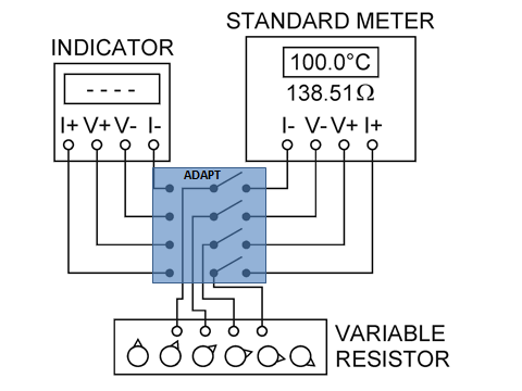
Figure 4: 4-wire PRT simulation using the standard to set the correct resistance value, before applying it to the unit under test.
Use 5: One set of terminals can be shorted together to be used for ‘zeroing’ a meter whilst the other set of terminals are used as the signal input. See figure 2 and figure 3B.
Use 6: Calibration of 3-wire PRTs using a 4-wire resistance meter can be performed. ‘Measurement 2’ in Figure 6 below is how the ADAPT should be wired and ‘Measurement 1’ illustrates how the first measurement is made but for clarity does not show the connections required for ‘Measurement 2’. The value from ‘Measurement 1’ has the lead wire error in it of 0.31ohms. ‘Measurement 2’ measures the common lead wire resistance of 0.62 ohms which is twice the resistance of the third wire because the wires are twice as long. This value is therefore halved and taken away from ‘Measurement 1’ to give the correct resistance of the PRT.

Figure 6: 3-wire measurement using a 4-wire meter.